This August, I accomplished what I wanted for many years: I deleted the last cgo
dependency in Debian Code Search! This was made possible by Go’s recently
introduced SIMD support, because now we can implement the TurboPFor integer
compression format as efficiently — more efficiently, in fact, by using the
newer AVX512 instruction set! — as the reference implementation.
Background: Why does DCS need a fast Integer Codec?
Debian Code Search (DCS) is a search engine that allows searching all the Open
Source source code within Debian, with either literal search expressions or
regular expression search queries.
A search engine uses an inverted index: a map from term to documents containing
the term. Each document is typically represented most efficiently by using an
id, so the index consists of many lists of document ids.
When searching, it is important to quickly decode these lists to answer the
search query. However, there is a point of diminishing returns where the
decoding speed, even though it can still be measurably improved quite a bit, no
longer influences the overall query duration.
From 2012 (its inception) to 2019, Debian Code Search used to use a small index
format, and queries were fast because the index was kept entirely in RAM. In
2019, I implemented the new index
format, which adds an
on-disk positional index. For literal queries (78.2% of DCS queries), querying
the positional index on disk is faster than querying the non-positional index in
RAM.
The efficient encoding of the TurboPFor format makes it possible to fit such an
index on a mid-sized Hetzner server, which I rent with two 1 TB SSD disks. The
optimized decoder of the C TurboPFor library is what made decoding fast at query
time.
If you want to dive deeper into the algorithm, see this blog post from February
2019:
If you want to learn more about the positional index, see this blog post from
September 2019:
SIMD in Go
For many years, you had the following options for using SIMD instructions in Go:
- Hand-writing Go assembler code. This is only doable for
small functions, for example
bytes.IndexByte is implemented with
hand-written Go
assembly
(including AVX2).
- Generating Go assembler code with tools like Michael McLoughlin’s
“Avo�. This is how
crypto/internal/fips140/sha256 uses
AVX2. While
Avo generator code definitely is higher-level than hand-written assembly, it
is still too close to assembly for my taste.
- Use a C library via cgo so gcc or clang compiles
SIMD code. Debian Code Search used to use the
powturbo/TurboPFor
C library via cgo for the last 7 years.
The C TurboPFor library has served us well, but Debian Code Search was always
intended to be a project using Go, so I would prefer it if I did not have any C
code in the project.
Go 1.26 (released in February 2026) introduced the simd/archsimd package:
Go 1.26 introduces a new experimental simd/archsimd
package, which can be enabled by setting
the environment variable GOEXPERIMENT=simd at build time. This package
provides access to architecture-specific SIMD operations. It is currently
available on the amd64 architecture and supports 128-bit, 256-bit, and
512-bit vector types, such as Int8x16 and Float64x8, with operations such
as Int8x16.Add. The API is not yet considered stable.
— Go 1.26 Release Notes
For my 2019 TurboPFor analysis, I implemented goturbopfor, a native Go
teaching decoder (without any SIMD),
because I find Go code easier to follow than C code, especially optimized C
code. My implementation was intentionally not optimized so that the code was
easier to study.
The TurboPFor format/algorithm has a vector-optimized part: bitpacking comes in
a scalar variant (bitunpack32) and a vector variant
(bitunpack256v32),
where the vector variant is used for full blocks (256 values) and the scalar
variant is used for remainder blocks (< 256 values).
When Go 1.26 was released, I used Claude Code to explore whether my native Go
decoder’s bitunpack256v32 function (for the vertical vector layout) could be
implemented using Go SIMD, and the answer was yes, it was possible and it was
faster than without SIMD, but not quite at the level of C TurboPFor. If you let
Claude Code try for long enough, it eventually finds enough optimizations (about
10) to match C performance.
I don’t want to vibe-code Debian Code Search, though, so I figured I would find
some time to review the SIMD code at some point and see if I could implement
something similar myself.
Before I found enough time and motivation to complete said review, I discovered
that to not regress real-life query performance by more than 10 to 100
milliseconds (which seems acceptable), I don’t actually need to add SIMD code to
my teaching decoder at all; it would be sufficient to reduce allocations in my
teaching decoder and specialize it per bit width.
Encouraged by the possibility of using the optimized native Go decoder in Debian
Code Search, I explored whether I could also implement a native Go encoder so
that I could get rid of the C TurboPFor dependency entirely. The answer is yes,
it is doable in a few days, and it isn’t even that much slower: Go is at 76% of
C, see Debian/dcs commit
e920dc7.
The goal I set myself at that point was to see if I could learn enough SIMD to
optimize the native Go encoder such that its performance would match how DCS
uses C TurboPFor (via cgo).
Beating C TurboPFor was possible in 2-3 commits (SIMD and bit width
specialization). To my surprise, Claude Fable 5 pointed out that the encoder’s
block scanning could be done more efficiently using a technique called
positional popcount, and that is another 2x speed-up! 😲
To be clear: I am not saying the Go compiler beats C here. Certainly, the C
compiler can also produce fast AVX512 code and can be used to implement
positional popcount. When comparing apples to apples, i.e. backporting the
AVX512 kernels and positional popcount technique to C TurboPFor, Go benchmarks a
little slower at ≈1.4x C.
This spectacular result (much faster than what DCS had before) got me curious
how far I could push the decoder with SIMD after all. I ended up
matching/exceeding the cgo version here, too!
The rest of this article explains a few classes of optimizations I encountered
along the way.
Starting Point
When I wrote my goturbopfor teaching
decoder, I named its functions to
match the upstream C TurboPFor library, but now I want to get away from names
like p4ndec256v32 — they make sense from the TurboPFor perspective, but for
Debian Code Search, we can use cleaner names.
Before writing any code, I audited how DCS uses integer compression /
decompression.
API design: BlockEncoder, BlockDecoder and streaming
In Debian Code Search, we have the following usage patterns:
- Partial Indexing: When a new package (or package version) enters Debian,
all of its (text) files are indexed. If the
hello-2.12.3-1
package (hypothetically) contained
only hello.c with printf("hello!\n");, we would assign document ID 1 to
hello.c and store in the partial index that trigrams pri, rin, int,
ntf, etc. are all found in doc 1 (hello.c).
- Full Index Merging: The many thousands of partial index files (for each
Debian package) are combined into a small handful of large index files: When
searching, it would be expensive to consult thousands of indexes. To merge
multiple partial index files into one larger index (which can then be
efficiently queried), we need to re-encode the partial index files: what used
to be document ID
1 in the partial index might be document ID 2531 in the
full index.
- Querying (searching): When users enter search queries, these queries need
to be answered as quickly as possible. The relevant entries in the full
indexes are decoded (in parallel).
For reading the index, we do keep the decoded uint32s fully in memory, so we
only need DecodeN(input []byte, output []uint32) (read int), a function that
reads len(output) values (uint32) from input and returns how many bytes it
consumed.
For writing the index (both in partial indexing, and when merging), keeping the
entire index in memory is prohibitively expensive, so we need a streaming API,
for decoding and for encoding.
Ultimately, I converged on the following API:
package pforenc

type BlockEncoder struct {
    // scratch buffers can go here
}

// EncodeBlock encodes len(vals)<=256 uint32s into dest (one TurboPFor block).
func (*BlockEncoder) EncodeBlock(dest []byte, vals []uint32) []byte {}

// EncodeN calls EncodeBlock in a loop.
func (*BlockEncoder) EncodeN(dest []byte, vals []uint32) []byte {}

type StreamEncoder struct {
  be   BlockEncoder
  vals [256]uint32
  // scratch buffers
}

// if full, you need to call [EncodeBlock]
func (*StreamEncoder) Add(val uint32) (full bool)

// EncodeBlock must be called after all data was [Add]ed.
//
// Write the returned buffer to file or send it over the network;
// it is only valid until the next [EncodeBlock] call.
func (*StreamEncoder) EncodeBlock() []byte {
  if se.n == 0 { return nil } // turn an extra EncodeBlock into a no-op
  // …
}
This API (the decoder works similarly) allows us to process data in TurboPFor
format without any memory allocations. The types are not safe for concurrent use
by multiple goroutines. The zero value is ready to be used. For the streaming
API, the result only stays valid until the next call.
Initial Implementation
Before we can optimize anything, we need a working decoder and encoder. The
decoder already exists: my goturbopfor teaching decoder. Next up, I needed an
encoder.
Writing a TurboPFor encoder has a delightfully simple starting point: You can
encode all values at bit width 32, in little endian, at which point you only
need to add a one-byte TurboPFor block header every 256 values and you’re done:
func (be *BlockEncoder) EncodeN(dest []byte, vals []uint32) []byte {
  for len(vals) > 0 {
    chunk := min(len(vals), 256)
    dest = be.EncodeBlock(dest, vals[:chunk])
    vals = vals[chunk:]
  }
  return dest
}

func (be *BlockEncoder) EncodeBlock(dest []byte, vals []uint32) []byte {
  const bitWidth = 32
  dest = append(dest, bitWidth)
  for _, val := range vals {
    dest = binary.LittleEndian.AppendUint32(dest, val)
  }
  return dest
}
Of course, this is a terribly inefficient compressor, so after the first commit,
the real work starts: implement each block type until the compression matches
the original C TurboPFor implementation (same output file size), or in other
words: do the reverse of the decoder.
- The TurboPFor bitpacking block type (bitpacking implementation
commit)
encodes a bit stream of variable bit width (where the bit width is in range
0 ≤ bitWidth ≤ 32) in little
endian byte order. By scanning all
values and choosing the smallest bit width that allows representing all
values, this technique saves disk space (compresses).
- The bitpacking with exceptions block type (bitpacking with exceptions
implementation
commit)
determines two bit widths: one for values, the other bit width for encoding
exceptions. This allows choosing a lower bit width (that does not cover all
values) compared to the bitpacking block type. A bitmap encodes whether a
value has an exception or not.
- The bitpacking with VB exceptions block type (bitpacking with VB
exceptions implementation
commit)
is a variant which does not use an exception bitmap and encodes exceptions
using a variable byte integer encoding. This is more efficient when there are
few exceptions (less than 20) or the exceptions are very different in bit
width compared to the other values.
- Lastly, the constant block type (constant implementation
commit)
stores just one value on disk. This is useful for all-zero or all-one blocks,
for example.
I found it interesting to realize that the main work of the encoder is to scan
the input values and choose the optimal block type, whereas the actual encoding
itself is cheap in comparison.
At this point, we can look at
performance
and see that the Go encoder is at 76% of the C encoder.
In all honesty, I could have probably stopped here, but now that the milestone
of a viable replacement was reached, I got curious to see how far it would be
possible to push the encoder (how much work to reach C speeds?) and afterwards,
the decoder, too.
Setup
The microarchitecture level: set GOAMD64
The microarchitecture of a CPU determines which instructions it provides, and
that includes not just SIMD instruction sets (like AVX2), but also other useful
instructions like LZCNT (Leading Zero Count), which can be used to implement
math/bits.Len32 more efficiently, which
the TurboPFor encoder needs to call on every input value to determine the ideal
bit width.
Let’s walk through how to set the microarchitecture level when using Go on
64-bit x86 (x86-64).
Go uses the GOARCH environment
variable to configure the target
compilation architecture, and I am using the value amd64 to select 64-bit x86
(AVX2 and AVX512 are instruction sets found on x86-64 CPUs). With
GOARCH=amd64, the architecture-specific variable
GOAMD64 configures the
microarchitecture level for which to compile and Go 1.18 introduced these 4
different levels:
GOAMD64=v1 (default): The baseline.
Exclusively generates instructions that all 64-bit x86 processors can execute.
GOAMD64=v2: all v1 instructions,
plus CMPXCHG16B, LAHF, SAHF, POPCNT, SSE3, SSE4.1, SSE4.2, SSSE3.
GOAMD64=v3: all v2 instructions,
plus AVX, AVX2, BMI1, BMI2, F16C, FMA, LZCNT, MOVBE, OSXSAVE.
GOAMD64=v4: all v3 instructions,
plus AVX512F, AVX512BW, AVX512CD, AVX512DQ, AVX512VL.
In 2026, I generally recommend compiling with GOAMD64=v3 so that functions
like bits.OnesCount8 are
compiled into intrinsics
(POPCNT)
instead of using a lookup table.
For Intel CPUs, setting GOAMD64=v3 means your programs will only start on
Haswell CPUs (2013) or newer; for AMD CPUs that means Zen 1 (2017) or newer.
In this specific case (DCS), I am even compiling with GOAMD64=v4. The v4
microarchitecture level requires AVX512, which means AMD Zen 4, Zen 5 or newer
(Intel’s story is… complicated). Luckily, both my main development PC (Zen 5)
and the Debian Code Search server (Zen 4) are recent enough. Setting
GOAMD64=v4 has little effect on Go 1.27 itself: the only change is that maps
use one less instruction (VPBROADCASTB instead of PSHUFB). But compiling
with GOAMD64=v4 allows us to move one more feature check from runtime to
compile time, see SIMD build tags.
It makes sense to set the microarchitecture level in your benchmark setup so
that you don’t measure the slow fallback implementations. I use export GOAMD64=v4 in my Makefile.
Benchmarking setup
Go’s built-in testing package contains support for
benchmarks which are written in
functions of the form func BenchmarkXxx(b *testing.B). The simplest way to run
such benchmarks is go test -bench=., but I ended up configuring a few
convenience make targets, which write results to bench.txt and compare
against baseline.txt (the previous commit’s results, usually), using the very
useful benchstat tool.
GOTEST=go test

# -count=6 gives p≤0.002 in benchstat:
# https://pkg.go.dev/golang.org/x/perf/cmd/benchstat
BENCHFLAGS=-run=^$$ -bench=. -benchtime=200000x -count=6

# use taskset -c1 to always pin to the same single core,
# avoiding accidental scheduling on different cores on
# mixed-core CPUs like the Ryzen 9 9950X3D.
TASKSET=taskset -c 1
BENCH=$(TASKSET) $(GOTEST) $(BENCHFLAGS)

.PHONY: all test bench bench-baseline bench-relative

all: test

bench: test
	$(BENCH) | tee bench.txt
# Compares compression ratio between C and Go implementation
	benchstat -col /impl -row '/n /vals' -filter '-/impl:go-stream .unit:(encoded-bytes)' bench.txt
# Compares performance between C (cgo) and Go implementation
	benchstat -col /impl -row '/n /vals' -filter '.unit:(Mval/s)' bench.txt

bench-baseline: test
	$(BENCH) | tee baseline.txt

bench-relative: test
	$(BENCH) | tee bench.txt
	benchstat -filter '-/impl:go-stream .unit:(encoded-bytes)' baseline.txt bench.txt
	benchstat -filter '/impl:go .unit:(Mval/s)' baseline.txt bench.txt
The encoded-bytes and Mval/s units are custom metrics I am reporting from
the various sub-benchmarks, which are arranged
such that I can filter / report them with benchstat.
The main encoder (and decoder) benchmarks compare 3 different implementations
(cgo, Go, Go with the StreamEncoder API) with a number of benchmark
cases
that are designed to cover the different block types and contain a similar mix
of values as what we see in Debian Code Search:
// reportMetrics adds Mval/s and encoded-bytes metrics to all benchmarks.
func reportMetrics(b *testing.B, n int, nencoded int) {
   b.ReportMetric(float64(nencoded), "encoded-bytes")
   b.ReportMetric(float64(b.N*n)/1e6/b.Elapsed().Seconds(), "Mval/s")
}

// BenchmarkEncode/n=<N>/vals=<testcase>/impl=<c|go|go-stream>
//
// e.g. BenchmarkEncode/n=2048/vals=one-constant/impl=go-stream
func BenchmarkEncode(b *testing.B) {
   for _, tc := range allBenchCases() {
     n := len(tc.vals)
     b.Run(fmt.Sprintf("n=%d/vals=%s", n, tc.name), func(b *testing.B) {
       b.Run("impl=c", func(b *testing.B) {
         b.ReportAllocs()
         var encoded []byte
         buf := make([]byte, turbopfor.EncodingSize(n))
         for b.Loop() {
           encoded = turbopfor.P4nenc256v32Buf(buf, tc.vals)
         }
         reportMetrics(b, n, len(encoded))
       })
       b.Run("impl=go", func(b *testing.B) {
         b.ReportAllocs()
         var be BlockEncoder
         var encoded []byte
         buf := make([]byte, 0, turbopfor.EncodingSize(n))
         for b.Loop() {
           encoded = be.EncodeN(buf, tc.vals)
         }
         reportMetrics(b, n, len(encoded))
       })
       b.Run("impl=go-stream", func(b *testing.B) {
         b.ReportAllocs()
         var se StreamEncoder
         var encoded int
         for b.Loop() {
           encoded = 0
           for _, val := range tc.vals {
             if se.Add(val) {
               encoded += len(se.EncodeBlock())
             }
           }
           encoded += len(se.EncodeBlock())
         }
         reportMetrics(b, n, encoded)
       })
     })
   }
}
CPU counters: perf
Go has included excellent performance tooling for many years, see the
“Profiling Go Programs� blog post (2011) for an
example of how to use pprof, a sampling profiler. This profiler can help track
down which part of a program runs slow, or where memory allocations happen.
Once you identified the slow part of a program, how do you know why it’s slow?
To learn more about the specific bottlenecks your program encounters, you can
consult your CPU’s hardware performance
counters. For
example, you could check the branch
predictor counters to see if
your program is slow due to a high number of branch mispredicts.
On Linux, the perf tool is the best way to access the CPU hardware performance
counters. A good starting point for working with perf is the documentation on
“Top-down analysis with the perf
tool�, which describes the
optimization method that Intel established.
In my Makefile, I set up two perf targets:
# GOTEST and TASKSET like shown in the earlier benchmarking setup section:
GOTEST=go test -pgo=encode.cpuprof
TASKSET=taskset -c 1
PERFBENCHFLAGS=-test.bench='Encode/n=2048/vals=debian-mix/impl=go$$' -test.benchtime=200000x

# Use perf(1) to capture AMD IBS (the equivalent to Intel PEBS)
# PipelineL1 is roughly equivalent to Intel TopdownL1
perf:
	$(GOTEST) -c
	$(TASKSET) perf stat -M PipelineL1 ./pforenc.test -test.run=^$$ $(PERFBENCHFLAGS)
	sudo perf record -F 4999 -e ibs_op// --call-graph fp ./pforenc.test -test.run=^$$ $(PERFBENCHFLAGS)
	sudo chmod 644 perf.data

# 488281 iterations × 2048 values = 1.000e9 values, so counter/1e9 = per value.
perf-per-value:
	$(GOTEST) -c
	$(TASKSET) perf stat -x, -e cycles:u,instructions:u,branches:u,branch-misses:u ./pforenc.test -test.run=^$$ -test.bench='Encode/n=2048/vals=debian-mix/impl=go$$' -test.benchtime=488281x 2>&1 >/dev/null | awk -F, '{printf "%-16s %6.2f /val\n", $$3, $$1/1e9}'
The perf-per-value numbers are high level numbers that indicate how much work
the implementation is doing. Reducing the number usually increases speed.
To see the counters for each instruction (and source code lines), I use make perf, followed by perf report. A quick shortcut is perf annotate, which
directly shows the hottest function.
Optimizations (scalar)
Let’s first see how far we can get without reaching for SIMD instructions.
(The examples are not necessarily in commit order, but cherry-picked for clarity.)
Profile-Guided Optimization (PGO)
PGO stands for Profile-Guided Optimization and is a feature that Go introduced
as a preview in Go 1.20 (released in February 2023) and shipped as ready for
general production use in Go 1.21 (released in August
2023).
The idea is to capture a CPU profile that records where your program spends most
of its CPU time, which you then provide to the Go compiler to give it more data
to make better decisions.
Most importantly, this way the Go compiler can inline functions much more
aggressively than its usual heuristics allow,
which does have a measurably positive effect in my series of optimization
commits. Another optimization that a PGO profile allows the compiler to do is
conditional devirtualization — but
our TurboPFor code does not use any interfaces.
My strategy is to enable PGO before doing any other optimizations, so that we
have the full inlining budget available that PGO gives us, and can measure the
effect of other commits clearly.
Surprisingly, turning on PGO actually decreases our
performance
(-13% geomean), but a closer investigation reveals that we just got unlucky. Let
me explain.
Aside from inlining and conditional devirtualization, PGO also influences
alignment: The Go compiler sets PCALIGNMAX(64, 31) on the first block of a
loop (the “loop body�) for all loops in hot functions (per the PGO profile),
i.e. Go will insert up to 31 bytes of padding to make the block land on a
64-byte boundary. Documentation like AMD’s “Software Optimization Guide for the
AMD Zen5 Microarchitecture� (2024,
#58455) explicitly recommends aligning hot loops that way:
[…] for hot loops, some further knowledge of trade-offs can be
helpful. Because the processor can read an aligned 64-byte fetch block every
cycle, it is suggested to either align the start of the loop to the beginning
of a 64-byte cache line […]
Indeed, when compiling with -gcflags=all=-d=alignhot=0 to disable the
alignment, performance remains as good as without PGO. How can the padding hurt
more than help? The answer is: It’s not the padding itself! It’s a side-effect
of the padding moving instructions to different addresses.
In the unlucky arrangement, a macro-fused CMPQ+JGE instruction pair now ends
up exactly on a 32-byte boundary. However, the Go compiler ensures fused
branch sequences must never cross or end at a 32-byte boundary to fix Intel
erratum
SKX102
(discussion: Go issue #35881) by
inserting NOPs.
This NOP padding, unlike the loop alignment padding, is not free; these extra
instructions slow down our otherwise dispatch-bound loops.
Because the commits after the PGO enabling commit change the code, this unlucky
situation is avoided for the rest of the optimization series (by chance).
Reducing memory allocations
Memory allocations are quite expensive, at least in comparison to
encoding/decoding integers, so I followed my usual strategy of first reducing
memory allocations as much as possible.
In my goturbopfor teaching decoder, whenever the code needed a scratch buffer,
it would allocate it right then and there with make():
// p4dec32 decodes one block of TurboPFor-encoded 32 bit ints
func (d *decoder) p4dec32(input []byte, output []uint32) (read int) {
    // …
  switch blockType {
  case blockBitpackingExceptions:
    bx, input := input[0], input[1:]
    n := len(output)

    exmap := input
    nex := 0 // number of exceptions
    for i := 0; i < n; i++ {
      if exmap[i/8]&(1<<uint(i%8)) != 0 {
        nex++
      }
    }
    input = input[(n+7)/8:]

    exceptions := make([]uint32, nex)
    input = input[bitunpack32(input, exceptions, bx):]
    input = input[d.bitunpack(input, output, b):]

    for i := 0; i < n; i++ {
      if exmap[i/8]&(1<<uint(i%8)) != 0 {
        output[i] += exceptions[0] << b
        exceptions = exceptions[1:]
      }
    }

    return before - len(input)
  }
}
The Go compiler can turn make(T, n) calls into stack allocations, if n is
known at compile-time. But, in this case nex is not known at compile-time. We
can verify that Go calls into the runtime (runtime.makeslice) by dumping the
object code (assembly) with source annotated (-S):
% cd ~/go/src/github.com/stapelberg/goturbopfor
% git reset --hard 49b7c05cc61e77f0257568eb73833467714d2b4a
% go test -c  # go1.27.0
% go tool objdump -S goturbopfor.test | perl -nlE 'say if /p4dec32/ .. /^$/'
TEXT github.com/stapelberg/goturbopfor.(*decoder).p4dec32(SB) /home/michael/go/src/github.com/stapelberg/goturbopfor/goturbopfor.go
func (d *decoder) p4dec32(input []byte, output []uint32) (read int) {
  0x549f60		4c8da42460ffffff	LEAQ 0xffffff60(SP), R12
  0x549f68		4d3b6610		CMPQ R12, 0x10(R14)
  0x549f6c		0f86d9070000		JBE 0x54a74b
  0x549f72		55			PUSHQ BP
  0x549f73		4889e5			MOVQ SP, BP
  0x549f76		4881ec18010000		SUBQ $0x118, SP
  0x549f7d		48899c2430010000	MOVQ BX, 0x130(SP)
  0x549f85		4889b42448010000	MOVQ SI, 0x148(SP)
	if len(output) == 0 {
  0x549f8d		4d85c0			TESTQ R8, R8
  0x549f90		0f84a7030000		JE 0x54a33d
  0x549f96		660f1f840000000000	NOPW 0(AX)(AX*1)
  0x549f9f		90			NOPL
[…]
		exceptions := make([]uint32, nex)
  0x54a4be		488d057bec1700		LEAQ 0x17ec7b(IP), AX
  0x54a4c5		4c89fb			MOVQ R15, BX
  0x54a4c8		4889d9			MOVQ BX, CX
  0x54a4cb		e8f0ddf3ff		CALL runtime.makeslice(SB)
[…]
An easy speed-up was to avoid allocations through
reuse
(in goturbopfor). In the DCS pfordec package (with the improved
API design), I ended up with a vals [256]uint32 field in the StreamDecoder
type, which brings us from 773 Mval/s to 858 Mval/s on the debian-mix:
% benchstat -filter '/impl:go /vals:debian-mix .unit:(Mval/s)' \
  baseline.txt bench.txt
goos: linux
goarch: amd64
pkg: github.com/Debian/dcs/internal/turbopfor/pfordec
cpu: AMD Ryzen 9 9950X3D 16-Core Processor
           │ baseline.txt │             bench.txt              │
           │    Mval/s    │   Mval/s     vs base               │
n=2048        1.089k ± 1%   1.175k ± 0%   +7.85% (p=0.002 n=6)
n=2039         974.7 ± 0%   1046.0 ± 0%   +7.32% (p=0.002 n=6)
n=160          434.9 ± 1%    513.6 ± 5%  +18.11% (p=0.002 n=6)
geomean        772.9         857.7       +10.98%
Aside from the speed-up, avoiding memory allocations is generally nice in
benchmarks because it removes the garbage collector from the equation and makes
it less likely that your benchmarks get other processes OOM-killed on the same
machine.
Generics for bit width specialization
In general, we want to make it easy for the compiler to understand as much as
possible about our algorithm. Consider this bitpack implementation:
func bitpack(dest []byte, vals []uint32, bitWidth int) []byte {
  mask := uint32(1<<bitWidth - 1)
  var acc uint64
  var have int
  for _, val := range vals {
    acc |= uint64(val&mask) << have
    have += bitWidth
    for have >= 32 {
      dest = binary.LittleEndian.AppendUint32(dest, uint32(acc))
      acc >>= 32
      have -= 32
    }
  }
  for have > 0 {
    dest = append(dest, byte(acc))
    acc >>= 8
    have -= 8
  }
  return dest
}
Let’s think through what determines the iterations and control flow this
function uses:
- The number of input values (
vals), but not their actual value.
- The bit width to pack into (
bitWidth).
With a bit of careful rearrangement, we can provide the compiler with both, a
fixed number of input values (say, 32), and a bit width, both known at compile
time. Why is this worthwhile? Because we can manually unroll the loop, let the
compiler eliminate much of the repetition and get much faster compiled code as a
result!
Let’s first fix the number of input values to 32 and rewrite the loop to
calculate the position offsets within dest instead of changing dest on each
value (with AppendUint32):
func bitpack32Unrolled(dest []byte, vals *[32]uint32, bitWidth int) {
  // only one bounds check for 32 values
  dest = dest[: 4*bitWidth : 4*bitWidth]
  mask := uint32(1<<bitWidth - 1)
  var acc uint64
  var have, pos int
  // Manually unrolled loop starts here.
  // Each iteration is identical except for the vals[x] index.
  acc |= uint64(vals[0]&mask) << have
  have += bitWidth
  if have >= 32 {
    binary.LittleEndian.PutUint32(dest[pos:pos+4], uint32(acc))
    pos += 4
    acc >>= 32
    have -= 32
  }

  // vals[1] .. vals[30] elided for brevity

  // Each loop iteration is 8 lines of Go code, so for 32 input values,
  // bitpack32Unrolled contains 8*32 = 256 lines of code.

  acc |= uint64(vals[31]&mask) << have
  have += bitWidth
  if have >= 32 {
    binary.LittleEndian.PutUint32(dest[pos:pos+4], uint32(acc))
    pos += 4
    acc >>= 32
    have -= 32
  }

  // have == 0; for all bitWidths
}
Next, we want to specialize not just for 32 input values, but also for each of
the 32 bit widths.
Can we do better than hand-copying bitpack32Unrolled 32 times (= 8192 lines of Go code)?
Yes, we can use Go generics to help us with the code generation!
In Go, array types like [4]byte (not
slices like []byte!) contain the length of the array as part of their type,
meaning [1]byte (an array of length 1) is a different type than [2]byte.
Instead of passing the bit width as a function parameter, we can declare 32
different types (one for each bit width) and recover the bit width (at compile
time!) from the type system:
type bitWidthT interface {
  [1]byte | [2]byte | [3]byte | [4]byte | [5]byte |
  [6]byte | [7]byte | [8]byte | [9]byte | [10]byte |
  [11]byte | [12]byte | [13]byte | [14]byte | [15]byte |
  [16]byte | [17]byte | [18]byte | [19]byte | [20]byte |
  [21]byte | [22]byte | [23]byte | [24]byte | [25]byte |
  [26]byte | [27]byte | [28]byte | [29]byte | [30]byte |
  [31]byte | [32]byte
}

func bitpack32Unrolled[T bitWidthT](dest []byte, vals *[32]uint32) {
  var zero T
  bitWidth := len(zero)                  // known at compile time
  dest = dest[: 4*bitWidth : 4*bitWidth] // make cap known at compile time
  mask := uint32(1<<bitWidth - 1)
  var acc uint64
  var have, pos int
  // Manually unrolled loop starts here.
  // Each iteration is identical except for the vals[x] index.
  acc |= uint64(vals[0]&mask) << have
  have += bitWidth
  if have >= 32 {
    binary.LittleEndian.PutUint32(dest[pos:pos+4], uint32(acc))
    pos += 4
    acc >>= 32
    have -= 32
  }

  // vals[1] .. vals[31] elided for brevity
}
When we instantiate bitpack32Unrolled[bitWidthT] with all 32 different types
([1]byte, [2]byte, …, [32]byte), the compiler substitutes the bitWidthT
type parameter and produces 32 copies of the function, which we can find in our
compiled executable with names like
github.com/Debian/dcs/internal/turbopfor/pforenc.bitpack32Unrolled[go.shape.[12]uint8]. The
“shape� of a generic type is based on its memory layout, so a shape for
[1]byte must be different than the shape for [2]byte.
Because the bitWidth is now known at compile time, the Go compiler can
generate close to the optimal machine code for each bit width, which we can
confirm using go tool objdump.
The code is branchless (after the one bounds check per 32 values) and aside from
the loads and stores (from/to memory) consists only of shifts and bit
operations, all with constant operands:
% go test -c && go tool objdump -S pforenc.test
[…]
TEXT github.com/Debian/dcs/internal/turbopfor/pforenc.bitpack32Unrolled[go.shape.[28]uint8](SB) /home/michael/dcs/internal/turbopfor/pforenc/bitpackunroll.go
func bitpack32Unrolled[T bitWidthT](dest []byte, vals *[32]uint32) {
  0x660580              55                      PUSHQ BP
  0x660581              4889e5                  MOVQ SP, BP
  0x660584              48895c2418              MOVQ BX, 0x18(SP)
        dest = dest[: 4*bitWidth : 4*bitWidth] // make cap known at compile time
  0x660589              4883ff70                CMPQ DI, $0x70
  0x66058d              0f820b030000            JB 0x66089e
        acc |= uint64(vals[0]&mask) << have
  0x660593              8b06                    MOVL 0(SI), AX
  0x660595              25ffffff0f              ANDL $0xfffffff, AX
        acc |= uint64(vals[1]&mask) << have
  0x66059a              8b4e04                  MOVL 0x4(SI), CX
  0x66059d              81e1ffffff0f            ANDL $0xfffffff, CX
  0x6605a3              48c1e11c                SHLQ $0x1c, CX
  0x6605a7              4809c8                  ORQ CX, AX
                acc >>= 32
  0x6605aa              4889c1                  MOVQ AX, CX
  0x6605ad              48c1e820                SHRQ $0x20, AX
                binary.LittleEndian.PutUint32(dest[pos:pos+4], uint32(acc))
  0x6605b1              90                      NOPL
        b[0] = byte(v)
  0x6605b2              890b                    MOVL CX, 0(BX)
        acc |= uint64(vals[2]&mask) << have
  0x6605b4              8b4e08                  MOVL 0x8(SI), CX
  0x6605b7              81e1ffffff0f            ANDL $0xfffffff, CX
  0x6605bd              48c1e118                SHLQ $0x18, CX
  0x6605c1              4809c1                  ORQ AX, CX
                acc >>= 32
  0x6605c4              4889c8                  MOVQ CX, AX
  0x6605c7              48c1e920                SHRQ $0x20, CX
                binary.LittleEndian.PutUint32(dest[pos:pos+4], uint32(acc))
  0x6605cb              90                      NOPL
        b[0] = byte(v)
  0x6605cc              894304                  MOVL AX, 0x4(BX)
Now we need to actually call bitpack32 from the general bitpack function:
func bitpack(dest []byte, vals []uint32, bitWidth int) []byte {
  if bitWidth == 0 {
    return dest // no payload, sparse block with only exceptions
  }
  if len(vals) >= 32 {
    size := 4 * bitWidth
    for len(vals) >= 32 {
      existing := len(dest)
      dest = slices.Grow(dest, size)[:existing+size]
      bitpack32(dest[existing:] /*append*/, (*[32]uint32)(vals), bitWidth)
      vals = vals[32:]
    }
  }
  mask := uint32(1<<bitWidth - 1)
  var acc uint64
  var have int
  for _, val := range vals {
    acc |= uint64(val&mask) << have
    have += bitWidth
    for have >= 32 {
      dest = binary.LittleEndian.AppendUint32(dest, uint32(acc))
      acc >>= 32
      have -= 32
    }
  }
  for have > 0 {
    dest = append(dest, byte(acc))
    acc >>= 8
    have -= 8
  }
  return dest
}

func bitpack32(dest []byte, vals *[32]uint32, bitWidth int) {
  switch bitWidth {
  case 1: bitpack32Unrolled[[1]byte](dest, vals)
  case 2: bitpack32Unrolled[[2]byte](dest, vals)
  case 3: bitpack32Unrolled[[3]byte](dest, vals)
  case 4: bitpack32Unrolled[[4]byte](dest, vals)
  case 5: bitpack32Unrolled[[5]byte](dest, vals)
  case 6: bitpack32Unrolled[[6]byte](dest, vals)
  case 7: bitpack32Unrolled[[7]byte](dest, vals)
  case 8: bitpack32Unrolled[[8]byte](dest, vals)
  case 9: bitpack32Unrolled[[9]byte](dest, vals)
  case 10: bitpack32Unrolled[[10]byte](dest, vals)
  case 11: bitpack32Unrolled[[11]byte](dest, vals)
  case 12: bitpack32Unrolled[[12]byte](dest, vals)
  case 13: bitpack32Unrolled[[13]byte](dest, vals)
  case 14: bitpack32Unrolled[[14]byte](dest, vals)
  case 15: bitpack32Unrolled[[15]byte](dest, vals)
  case 16: bitpack32Unrolled[[16]byte](dest, vals)
  case 17: bitpack32Unrolled[[17]byte](dest, vals)
  case 18: bitpack32Unrolled[[18]byte](dest, vals)
  case 19: bitpack32Unrolled[[19]byte](dest, vals)
  case 20: bitpack32Unrolled[[20]byte](dest, vals)
  case 21: bitpack32Unrolled[[21]byte](dest, vals)
  case 22: bitpack32Unrolled[[22]byte](dest, vals)
  case 23: bitpack32Unrolled[[23]byte](dest, vals)
  case 24: bitpack32Unrolled[[24]byte](dest, vals)
  case 25: bitpack32Unrolled[[25]byte](dest, vals)
  case 26: bitpack32Unrolled[[26]byte](dest, vals)
  case 27: bitpack32Unrolled[[27]byte](dest, vals)
  case 28: bitpack32Unrolled[[28]byte](dest, vals)
  case 29: bitpack32Unrolled[[29]byte](dest, vals)
  case 30: bitpack32Unrolled[[30]byte](dest, vals)
  case 31: bitpack32Unrolled[[31]byte](dest, vals)
  case 32: bitpack32Unrolled[[32]byte](dest, vals)
  }
}
Encoding remainder blocks is quite a bit faster (full blocks use the vertical
layout anyway):
% benchstat -filter '/impl:go /n:160 .unit:(Mval/s)' baseline.txt bench.txt
goos: linux
goarch: amd64
pkg: github.com/Debian/dcs/internal/turbopfor/pforenc
cpu: AMD Ryzen 9 9950X3D 16-Core Processor
                         │ baseline.txt │             bench.txt              │
                         │    Mval/s    │   Mval/s     vs base               │
vals=bitpacking-bw1          751.2 ± 3%   1120.5 ± 0%  +49.15% (p=0.002 n=6)
vals=bitpacking-bw2          716.8 ± 2%   1176.0 ± 0%  +64.07% (p=0.002 n=6)
vals=bitpacking-bw7          700.0 ± 1%   1078.5 ± 0%  +54.08% (p=0.002 n=6)
vals=bitpacking-bw1-exc      524.8 ± 1%    736.8 ± 0%  +40.40% (p=0.002 n=6)
vals=bitpacking-bw2-exc      543.7 ± 1%    758.2 ± 0%  +39.46% (p=0.002 n=6)
vals=bitpacking-bw7-exc      566.7 ± 1%    787.7 ± 0%  +38.99% (p=0.002 n=6)
vals=bitpacking-vb-exc       442.6 ± 1%    616.5 ± 0%  +39.29% (p=0.002 n=6)
vals=sparse-exc              532.4 ± 0%    787.8 ± 0%  +47.97% (p=0.002 n=6)
vals=sparse-vb-exc           408.9 ± 1%    597.8 ± 0%  +46.20% (p=0.002 n=6)
vals=debian-mix              559.5 ± 0%    783.8 ± 9%  +40.09% (p=0.002 n=6)
This performance win comes at the cost of binary size increase. In this case,
the .text section (executable code) grows by about 20 KB and the .gopclntab
section grows by another 26 KB. Definitely a price I am very willing to pay, but
the case might not be as clear in all circumstances.
Optimization: Bigger strides with SIMD
Even without reaching for SIMD instructions, a TurboPFor implementation can be
made faster by making it work bigger strides. Take this code from the
goturbopfor teaching decoder which counts the number of exceptions by checking
if each value’s bit is set in the exception bitmap:
case blockBitpackingExceptions:
  bx, input := input[0], input[1:]
  n := len(output)

  exmap, input := input, input[(n+7)/8:]
  nex := 0 // number of exceptions
  for i := range n {
    if exmap[i/8]&(1<<uint(i%8)) != 0 {
      nex++
    }
  }
  exceptions := d.scratch[:nex]
We can use the bits.OnesCount64
functions to count ones bits in the exception bitmap, 64 values at a time. For
remainder blocks, the rest is processed 8 values (1 byte) at a time:
i := 0
for ; i+8 <= n/8; i += 8 {
  xm8 := binary.LittleEndian.Uint64(exmap[i:])
  nex += bits.OnesCount64(xm8)
}
for ; i < (n+7)/8; i++ {
  xmb := exmap[i]
  // Clear the bits which do not belong to the exception map:
  if rem := n - i*8; rem < 8 {
    xmb &= 1<<rem - 1
  }
  // Go compiles OnesCount32 into an intrinsic,
  // but not OnesCount8, so we convert to uint32:
  nex += bits.OnesCount32(uint32(xmb))
}
OnesCount64 uses a 64-bit register. For comparison, AVX2 SIMD instructions use
256-bit registers (= 8 uint32) and AVX512 SIMD instructions use 512-bit registers.
In the following sections, we will first set up our build tags for conditional
compilation to use a trivial SIMD instruction, then walk through an AVX2 and
AVX512 SIMD kernel.
Let’s assume we have the following scalar code:
constant.go:
package pfordec

func fillConstant(output []uint32, val uint32) {
  for i := range output {
    output[i] = val
  }
}
To increase throughput, we can use AVX2 instructions if they are available on the CPU on which the program runs, i.e. using runtime dispatch. We’ll first rename fillConstant to fillConstantScalar (it’s now the fallback path):
constant.go:
package pfordec

func fillConstantScalar(output []uint32, val uint32) {
  for i := range output {
    output[i] = val
  }
}
Next, we’ll supply two different implementations (constant_nosimd.go and constant_amd64.go), the latter of which is selected when compiling for GOARCH=amd64 with GOEXPERIMENT=simd (the latter will hopefully be dropped in a later version of Go). The nosimd variant just dispatches to the fillConstantScalar, which will likely be inlined:
//go:build !goexperiment.simd || !amd64

package pfordec

func fillConstant(output []uint32, val uint32) {
  fillConstantScalar(output, val)
}
The constant_amd64.go variant assigns the hasAVX2 global variable by doing a CPUID check and then jumps to the scalar fallback if !hasAVX2, i.e. the CPU is too old:
//go:build goexperiment.simd && amd64

package pfordec

import "simd/archsimd"

var hasAVX2 = archsimd.X86.AVX2()

func fillConstant(output []uint32, val uint32) {
  if !hasAVX2 {
    fillConstantScalar(output, val)
    return
  }
  val8 := archsimd.BroadcastUint32x8(val)
  i := 0
  for ; i+8 <= len(output); i += 8 {
    val8.StoreArray((*[8]uint32)(output[i : i+8]))
  }
  // use the scalar implementation for the last <= 7 elements
  fillConstantScalar(output[i:], val)
}
We can go one step further by conditionally compiling const hasAVX2 = true
when GOAMD64 is set to v3 or higher (i.e. the amd64.v3 build tag is
set). As a practical example from Debian Code Search, we currently need the
following checks / dispatches:
| code |
function |
vector instruction set |
GOAMD64 |
| encoder |
bitpack256v |
AVX2 |
GOAMD64=v3 |
| encoder |
exbitmap |
AVX512 |
GOAMD64=v4 |
| encoder |
scan |
AVX512+VBMI+GFNI+BITALG |
n/a |
| decoder |
bitunpack |
AVX2 |
GOAMD64=v3 |
| decoder |
bitunpack256v32 |
AVX2 |
GOAMD64=v3 |
| decoder |
bitunpack256v32Ex |
AVX512 |
GOAMD64=v4 |
In DCS, the effect is measurably positive, but
small.
The 256 uint32 vertical layout
First, here is the layout explanation from my 2019 TurboPFor analysis blog
post:
In regular (non-SIMD) bitpacking, integers are stored on disk one after
the other, padded to a full byte, as a byte is the smallest addressable unit
when reading data from disk. For example, if you bitpack only one 3 bit int,
you will end up with 5 bits of padding.

SIMD bitpacking works like regular bitpacking, but processes 8 uint32
little-endian values at the same time, leveraging the AVX instruction
set. The following
illustration shows the order in which 3-bit integers are decoded from disk:

The scalar implementation uses an array of 8 uint64 to process 8 values at a
time:
func bitunpack256v32(input []byte, dest []uint32, bitWidth int) (read int) {
  mask := uint64(1)<<bitWidth - 1
  orig := len(input)
  var bits uint
  var acc [8]uint64 // accumulator: current+next bits
  for op := 0; op < len(dest); {
    if bits < uint(bitWidth) {
      // read 8 more uint32s
      for i := range 8 {
        acc[i] |= uint64(binary.LittleEndian.Uint32(input)) << bits
        input = input[4:]
      }
      bits += 32
    }
    for i := range 8 {
      dest[op] = uint32(acc[i] & mask)
      op++
      acc[i] >>= bitWidth
    }
    bits -= uint(bitWidth)
  }
  return orig - len(input)
}
The SIMD version also processes 8 values, but without a for i := range 8 loop!
One difference is that we no longer have the luxury of using uint64 for acc
(holding rest and current bits); because AVX2 registers only fit 8 uint32 (not
8 uint64). Instead, we split acc into rest8 and cur8.
func bitunpack256v32(fullinput []byte, fulldest []uint32, bitWidth int) (read int) {
  dest := fulldest[:256]
  if bitWidth == 0 {
    clear(dest)
    return 0
  }
  n := 32 * int(bitWidth)
  input := fullinput[:n] // tell the Go compiler how long the input is
  mask8 := archsimd.BroadcastUint32x8(uint32(1)<<bitWidth - 1)
  bitWidth8 := archsimd.BroadcastUint32x8(uint32(bitWidth))
  var bits uint
  pos := 0
  // var acc [8]uint64
  var rest8 archsimd.Uint32x8
  var cur8 archsimd.Uint32x8
  for op := 0; op < 256; op += 8 {
    if bits < uint(bitWidth) {
      // read 8 more uint32s
      // acc[i] |= uint64(binary.LittleEndian.Uint32(input)) << bits
      next := archsimd.LoadUint8x32(input[pos : pos+32]).ReshapeToUint32s()
      pos += 32  // input = input[4:]
      cur8 = rest8.Or(next.ShiftAllLeft(uint64(bits)))
      // acc[i] >>= bitWidth
      rest8 = next.ShiftAllRight(uint64(uint(bitWidth) - bits))
      bits += 32
    } else {
      cur8 = rest8
      // acc[i] >>= bitWidth
      rest8 = rest8.ShiftRight(bitWidth8)
    }
    // dest[op] = uint32(acc[i] & mask)
    cur8.And(mask8).Store(dest[op : op+8])
    bits -= uint(bitWidth)
  }
  return n
}
The SIMD version benchmarks about 3x as fast as the scalar version.
Another significant speedup is to use generics for bit width
specialization for this SIMD kernel so that
bitWidth becomes a compile-time constant and the compiler can generate better
code.
Positional Popcount
For my TurboPFor encoder, I implemented the same techniques as described above:
-
Bitpack full blocks with SIMD (AVX2)
-
Gather exceptions using SIMD (AVX512)
-
Use generics to specialize per bit width
These changes are sufficient to roughly match the cgo performance, but then
Claude Fable 5 found another 2x speed-up on top of that!
The key observation is that once encoding blocks is fast, the preceding step of
scanning the input values to decide which block type to use becomes the
bottleneck. Here is the encoder’s main encode function, which first does one
pass over the input values (scan) and then prices all different block types at
all relevant bit widths (requires fast access to the scan histogram):
func (be *BlockEncoder) encode(dest []byte, vals []uint32, layout blockLayout) []byte {
  var stats stats
  scan(&stats, vals) // gathers statistics from every value in vals
  bitWidth := bits.Len32(stats.or)
  if stats.or == stats.and {
    return be.encodeConstant(dest, vals, bitWidth)
  }
  n := len(vals)
  // bitpacking is the default, unless we find a more efficient block type.
  bestType := blockBitpacking
  bestB := bitWidth
  best := priceBitpack(n, bitWidth, layout)

  // Walk from high bitWidths to low: to break ties, we prefer
  // the encoding with fewer exceptions (for faster decoding).
  for b := bitWidth - 1; b >= 0; b-- { // up to 32 iterations
    nex := int(stats.cnt[b])
    size := priceBitpackExceptions(n, b, bitWidth, nex, layout)
    if size < best {
      bestType = blockBitpackingExceptions
      bestB = b
      best = size
    }
    // Over-approximate the number of VB bytes.
    vb := nex + // exceptions using 1, 2, 3, 4, or 5 VB bytes
      int(stats.cnt[b+7]+ // exceptions using 2, 3, 4, or 5 VB bytes
        stats.cnt[b+14]+ // exceptions using 3, 4, or 5 VB bytes
        stats.cnt[b+19]+ // exceptions using 4 or 5 VB bytes
        stats.cnt[b+24]) // exceptions using 5 VB bytes
    size = headerBytes + headerExBytes + payloadBytes(n, b, layout) + vb + nex
    if size < best {
      bestType = blockBitpackingVBExceptions
      bestB = b
      best = size
    }
  }
  switch bestType {
  case blockBitpacking:
    return be.encodeBitpack(dest, vals, layout, bitWidth)
  case blockBitpackingExceptions:
    return be.encodeBitpackExc(dest, vals, layout, bestB, bitWidth-bestB)
  case blockBitpackingVBExceptions:
    return be.encodeBitpackVBExc(dest, vals, layout, bestB, int(stats.cnt[bestB]))
  default:
    panic("BUG: bestType not implemented")
  }
}
I’ll show you a slightly shortened version of scan, the function which is the bottleneck:
type stats struct {
  // cnt[n] = how many values where bits.Len32(val)>n,
  // i.e. how many exceptions are required for bitWidth=n.
  // Padded so that cnt[b+24] is always in bounds.
  cnt [32 + 24]uint32
}

func scan(output *stats, vals []uint32) {
  for _, val := range vals {
    for b := range bits.Len32(val) {
      output.cnt[b]++ // b bits are not enough to store val
    }
  }
}
Let’s consider the following 3 example values to understand the resulting cnt:
| input |
input (bin) |
bits.Len32 |
| 23 |
0b0000010111 |
5 |
| 5 |
0b0000000101 |
3 |
| 666 |
0b1010011010 |
10 |
The resulting cnt exception count histogram would contain (cnt shortened to c):
c[0] |
c[1] |
c[2] |
c[3] |
c[4] |
c[5] |
c[6] |
c[7] |
c[8] |
c[9] |
c[10] |
| 3 |
3 |
3 |
2 |
2 |
1 |
1 |
1 |
1 |
1 |
0 |
In words, this means that at bit width 10, we could encode all the values
without any exceptions.
But most values do not need 10 bits, so a bit width of 5 would be more
efficient, but requires storing one exception. Encoding at bit width 4 requires
2 exceptions, and so on.
The scan function above is intentionally kept simple for illustration. We can
make it faster by moving the per-bit-width loop outside the per-element
loop.
The fast version still needs about 12 instructions per value. With SIMD, we can
reduce this to by 8x to only 1.5 instructions per value!
The trick: smear masks enable positional popcount
The trick is to turn each input value into its “smear mask� (imagine taking the
first 1 bit and smearing it across the remaining positions). Here are the smear
masks for our example:
| input |
input (bin) |
bits.Len32 |
“smear mask� |
| 23 |
0b0000010111 |
5 |
0b0000011111 |
| 5 |
0b0000000101 |
3 |
0b0000000111 |
| 666 |
0b1010011010 |
10 |
0b1111111111 |
Turning a value into its smear mask is computationally cheap:
Go implements BitLen(x) (functions like bits.Len32) by calculating 32 - LZCNT(x). We can calculate the “smear mask� of a value with ^uint32(0) >> LZCNT(x), i.e. starting with a 32-one-bits mask and shifting it by the number
of leading zeros.
Now, to obtain e.g. cnt[4], we can count the 1 bits at bit position 4 of all
input values.
The POPCNT instruction counts bits very efficiently, but it counts one bits
within a register, so it counts rows, not columns. Counting columns is called
Positional Population Count.
I found the following papers that describe positional popcount with SIMD:
- 2019: “Efficient Computation of Positional Population Counts Using SIMD
Instructions� (Klarqvist, Muła, Lemire)
introduces an AVX512 implementation using Carry-Save Adder
(CSA) networks, but in my
testing, that approach is slower for TurboPFor encoding.
- 2024: “Histogramming bytes with positional popcount (GF2P8AFFINEQB
edition)�
(Harold Aptroot) shared a C++
implementation illustrating the
technique I am using. If you are not familiar with how C++ vector intrinsics
look, take a look at this example.
- 2025: “Faster Positional-Population Counts for AVX2, AVX-512, and
ASIMD� (Clausecker, Lemire, Schintke)
improves performance over the 2019 paper, but cites the Aptroot blog post as
“Future Work�, promising even faster processing for smaller inputs.
Positional Popcount: a visual explanation
To understand the AVX512 implementation of positional popcount, I found it most
helpful to visualize an AVX512 register (512 bits, i.e. 64 bytes). The graphic
below uses the Uint64x8 layout, meaning it divides the register into 8 lanes
of 64 bits (= 8 bytes) each.
This illustration shows the whole process: how uint32s are loaded into an
AVX512 register (all 4 of its bytes, in sequence) and where we end up, i.e. the
32 positional popcounts:
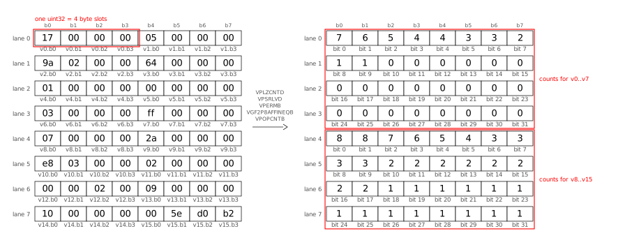
Let’s break down this process into its individual steps.
First, we turn each loaded value into its smear mask as explained above.
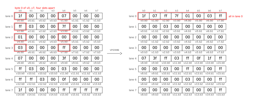
The VPOPCNTB vector instruction calculates POPCNT (1 byte) of 64 bytes at
once, but first we need to shuffle the bytes inside the register: in load
order, we have a full uint32 (4 bytes), followed by another uint32, per
lane. First, we permute the bytes (VPERMB) such that all the first bytes of
each value end up in one lane (“transpose the bytes�):
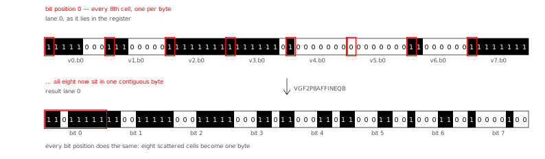
Next, we “transpose the bits� using the GF2P8AFFINEQB instruction, which
sounds scary but turns out to be quite flexible for bit manipulation of all
kinds. The GF2P8AFFINEQB instruction is also “the star of the show� in Go’s
Green Tea Garbage Collector (2025). Here is the
bit transpose, shown in the AVX512 register layout (see below for a different
layout):
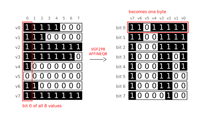
I found it easier to understand the transpose step when arranging the 8 bytes of
lane 0 from top-to-bottom (instead of left-to-right), because then it looks like
a 90 degree clockwise rotation:
Now we can use VPOPCNTB to count the bits in all 64 bytes at once:
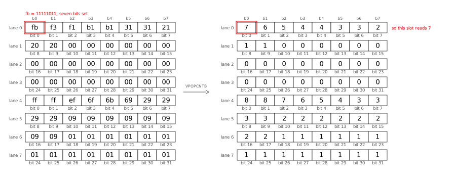
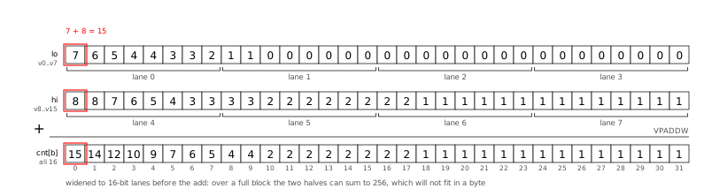
After all loop iterations (processing 16 values each) are done, we add the two
groups (first 8 values, second 8 values) to obtain the 32 exception counts:
Positional Popcount: Go SIMD
Here is the Go code that implements what I described visually above:
func scanSIMD(output *stats, vals []uint32) {
  ones16 := archsimd.BroadcastUint32x16(^uint32(0)) // 16 32-one-bits masks
  shuffle := archsimd.LoadUint8x64Array(&scanShuffle)
  units := archsimd.LoadUint8x64Array(&scanUnits)
  var acc archsimd.Uint8x64
  idx := 0
  for ; idx+16 <= len(vals); idx += 16 {
    v := archsimd.LoadUint32x16(vals[idx : idx+16])
    // Replace all values with their smear masks.
    smear := ones16.ShiftRight(v.LeadingZeros()).ReshapeToUint8s()
    // Transpose: shuffle the bytes, then transpose the bits.
    matrices := smear.Permute(shuffle).ReshapeToUint64s()
    transposed := units.GaloisFieldAffineTransform(matrices, 0)
    // Popcount 64 bytes at once into the accumulator.
    acc = acc.Add(transposed.OnesCount())
  }
  // Store the accumulator into output.cnt:
  // Widen the two groups of byte counts to uint16 lanes (so that
  // 128+128 = 256 fits), fold them into cnt[b] for b=0..31,
  // then widen again to the uint32 lanes of output.cnt.
  sum := acc.GetLo().ExtendToUint16().Add(acc.GetHi().ExtendToUint16())
  sum.GetLo().ExtendToUint32().Store(output.cnt[0:16])
  sum.GetHi().ExtendToUint32().Store(output.cnt[16:32])
  // scalar tail for the 0..15 remaining values
  for _, val := range vals[idx:] {
    for b := range bits.Len32(val) {
      output.cnt[b]++
    }
  }
}
Have a look at the commit introducing positional popcount to
DCS
for the full code (including shuffle tables and ISA checks) as well as the
detailed benchmark results.
Go even faster?
The SIMD optimizations I showed above beat the cgo TurboPFor library that Debian
Code Search used before. When comparing apples to apples, i.e. backporting the
AVX512 kernels and positional popcount technique to C TurboPFor, Go benchmarks a
little slower at ≈1.4x C.
Could we make my Go TurboPFor implementation even faster, to truly match the C
speed?
Yes! But also no. Let me explain:
-
We could use more SIMD instructions to remove all code that still processes
one value at a time. For example, in my encoder’s encodeBitpackVBExc
function. Or we could price all bit widths concurrently in encode. Or in
the decoder’s exception apply code path.
But all of these SIMD instructions
make understanding (and changing) the code harder, so I am cautious regarding
which ones I introduce.
-
A big part of the performance gap is due to Go’s bounds
checks. While it costs
performance, bounds checking is great for safety, so I will not turn off
bounds checking. The Go compiler eliminates a number of bounds checks when it
understands it’s safe to do so. One optimization avenue could be to make the
prove pass in the Go compiler smarter to eliminate more bounds checks.
-
When doing mid-stack inlining (proposal
#19348)
(2017), Go sometimes needs to put NOP instructions into the binary so that
it can attach inlining markers. For dispatch-bound functions, these extra
NOPs can measurable slow down execution.
-
The Go compiler currently allows specifying the architecture (GOARCH=amd64)
and microarchitecture (GOAMD64=v3), but not a specific CPU architecture
(like AMD Zen 4). Therefore, CPU-specific workarounds for one vendor affect
all the generated code. The specific one I encountered in my code is that the
Go compiler emits XORL CX,CX before every POPCNT to break a
false-output-dependency from the Intel Sandy Bridge Skylake era, which is
unnecessary on AMD Zen CPUs.
I suspect that Go intentionally does not offer this level of customizability.
-
After all of the above points are addressed, what remains is better code
generation in specific cases. To illustrate what I mean, consider the example
of incrementing a loop variable, where Go re-derives an index every time:
Go: POPCNTL; ADDQ DI,CX; LEAQ (base)(CX*4) (3 instructions)
clang: popcnt; lea rax,[rax+4*rdi] (2 instructions)
Depending on the specific case, improving the compiler might be easy or
prohibitively complex. Often, such improvements are hard to measure conclusively.
Conclusion
Go’s SIMD support makes available — in Go code without having to resort to cgo
or assembly — a powerful part of modern CPUs which allows speeding up the kind
of computation that TurboPFor needs by an order of magnitude! 😲
I found it very valuable to use a coding agent (Claude Code, with Opus 5 and
Fable 5 in this case) to help with the many tedious parts of such performance
work (and still it took me weeks!). The LLM can read objdump output much faster
than I can, can see patterns and correlations I might never identify, never
becomes frustrated after a compiler error or runtime panic, and never runs out
of patience to run one more experiment, as long as I give it measurable and
reachable goals.
The performance of the SIMD code which one can get from the Go compiler is
pretty close to what a good C compiler like clang provides. The CPU performance
counters show value decoding speeds of 7 instructions/cycle (IPC) on a machine
where the maximum is 8 IPC.
To me, SIMD support is a very welcome addition to Go.






















![VMS Enterprises Ltd vs The Brexit Party Ltd ([2021] SC GLA 49), 11694875, 16260766, CR-2022-003973](https://danielpocock.com/assets/reform-uk/2021scgla49-vms-enterprises-ltd-against-the-brexit-party-ltd-cover.jpg)
![Reform UK, Nigel Farage, creditors, [2021] SC GLA 49](https://danielpocock.com/assets/reform-uk/vms-brexit-research-article.jpg)


![Reform UK, Nigel Farage, Brexit Party, 11694875, 16260766, CR-2022-003973, [2021] SC GLA 49](https://danielpocock.com/assets/reform-uk/gazette-side-by-side.png)
















![[RSS 1.0 Feed]](common/rss10.png)
![[RSS 2.0 Feed]](common/rss20.png)
![[Atom Feed]](common/atom.png)
![[FOAF Subscriptions]](common/foaf.png)
![[OPML Subscriptions]](common/opml.png)
![[Hacker]](common/hacker.png)
![[Planet]](common/planet.png)